
- #Gns3 labs for ccna security how to
- #Gns3 labs for ccna security serial
- #Gns3 labs for ccna security Pc
- #Gns3 labs for ccna security windows
Before continuing, we can rename the devices, and adding some textlabels to the topology, so it looks something like the screenshot below.Ĭonfiguring the Cloud devices and Virtual PC Simulator The Topology Summary on the right side gives a good overview which interface is connected to which, on which device.
#Gns3 labs for ccna security serial
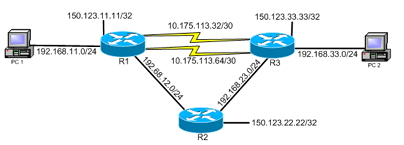
Now we have the routers connected in a triangle, using their serial interfaces. Create the other two serial connections in the same way. Now we create the serial links, by clicking on the “Add a link” button, and choosing “Manual”, then when clicking on R1, we choose s0/0 from the list of interfaces, then click on R2, selecting the interface we want to connect to, in this case s0/1. (But do remember and really note, “Now I connect this to that using a crossover cable.” (even if you really don’t see it, in GNS3) when you build the topology, to get it in your head properly and not get bad habits.) Creating the serial links In GNS3 cabletype is insignificant, we will therefor connect the simulated PC:s directly to the routers instead. We skip the switches completely, as they are only there to make it possible to not use any crossover cables in this (and many other) labs. After adding the three routers, add two Cloud units, they will be our simulated PC:s. I use the “Router c2600” with a “” IOS image. The first thing we do is add the three routers, using a model, with an IOS image that you have already configured. Choose an appropriate name, like “testlab_ppp”, remember to check the “Export router configuration files” checkbox. Upon start we are asked to either name, and create a new project, or open an existing one. When starting GNS3 we have an empty working space. This is the topology that we will use, as shown in the CCNA4 curriculum lab manual.

When you have a router set up and configured with an IDLE PC value that doesn’t consume all your processor cycles, continue building the topology in GNS3, as follows. Also remember to add a WIC-2T card to the router, or make sure it has two serial interfaces.
#Gns3 labs for ccna security how to
Read the “Creating the Simplest Topology” section of the PDF linked above to learn how to accomplish that. The first thing you should do is following the documentation of GNS3, to set up a router with an IOS image, and set it’s IDLE PC value.

#Gns3 labs for ccna security windows


 0 kommentar(er)
